
Transient Electromagnetic or
Time-Domain EM (TEM)
Overview
The transient electromagnetic (TEM) method, alternately called time-domain EM (TDEM) or pulse EM (PEM), is a commonly-used, non-intrusive, geophysical method for obtaining subsurface resistivity-conductivity data.
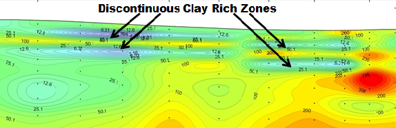
Because rock conductivity strongly correlates to rock properties, TEM is an effective way to map changes within rock or soil, for example, clayey layers restricting groundwater flow, conductive leachate in groundwater, and seepage in earthen embankments.
TEM methods have been used in mineral exploration for more than half a century and are now used for an extremely broad range of applications in exploration, engineering, and environmental investigation.
The depth of investigation can vary from 10s of meters to over 1000 meters (30 to 3,000 feet), depending upon the size of the transmitter loop being used, available power from the transmitter, and ambient electromagnetic noise. Zonge uses NanoTEM®, a fast-turn-off variation of TEM for very shallow surface applications (<5 meters).
How it works
 TEM requires
a specialized transmitter to drive a time-varying current into a transmitter loop, usually an ungrounded loop of wire laid on the surface. The transmitter loop generates an EM wave that propagates into the subsurface. As the EM energy encounters different subsurface materials, it induces eddy currents that generate secondary EM fields. These secondary EM fields are picked up at the surface by a receiver loop or magnetic antenna and recorded as the induced energy diffuses into the earth. The rate of diffusion indicates the resistivity of the subsurface materials.
Applications
TEM techniques are used to map geologic structure in search of geothermal sources, groundwater, and aggregate deposits. Environmental and engineering uses range from delineating salt-water intrusion and contaminant migration to determining permafrost and depth to bedrock. more
A strength of TEM is in revealing conductive objects embedded in a resistive background. Hence it is also the preferred method for locating buried metal objects such as abandoned wells, pipelines, UST (underground storage tanks) and UXO.
TEM advantages over DC resistivity
The TEM/TDEM method has several advantages over the DC resistivity technique. TEM does not require long electrode arrays and so is less sensitive to lateral changes in soils. DC resistivity requires long electrode spreads with lengths that are typically three to five times the depth of exploration. more
Thus, investigating to depths of 200 feet with DC resistivity requires an area of uniform horizontally-stratified soils with a lateral extent in excess of 600 feet. In contrast, the TEM method can obtain depths of exploration of several 100 feet with a 50-foot transmitter loop.
TEM has better depth resolution than DC resistivity, particularly for mapping conductive aquitards (confining layers) in resistive sections. Whereas the DC technique has difficulty mapping strata below a resistive layer, TEM can easily map conductive strata beneath a thick resistive section.
Logistics
Field logistics vary, but all configurations are non-intrusive and low-impact. For large-scale, deep-sounding TEM surveys, a typical Zonge field crew consists of three or four people, with one pick-up truck at the transmitter site and one at the receiver site. No off-road driving is necessary. more
Equipment for the receiver site is carried by backpack. For near-surface surveys using fast-turn-off equipment — such as the Zonge Dynamic NanoTEM® transceiver — only one or two people may be required.
Equipment consists of a transmitter, a receiver, a transmitting wire loop, and a receiving wire loop (or magnetic coil sensor). Equipment configuration varies greatly including the use of large stationary loops on the ground, cart-mounted systems, and boat-towed loops for marine applications. Large loops allow a greater depth of investigation but are more time consuming to set up.
When not cart-mounted or towed, the transmitter wire is simply a thin, insulated wire laid out on the ground by walking. Vehicle access along the length of the transmitter is not necessary. Unlike reconnaissance CSAMT, TEM measurements are made one station at a time, but the measurements are made quickly since each transient is equivalent to a wide spectrum of individual frequency measurements.
Principles
The TEM method begins with transmitting a time-domain, square-wave signal into a large ungrounded loop. At some point, the loop current is interrupted as fast as possible thereby causing a rapid change in the magnetic field generated by the transmitter. more
Faraday’s law of induction tells us that a changing magnetic field will produce an electric field, which in turn will create an electric current. Thus the rapidly changing magnetic field induces eddy-currents to flow in nearby conductors producing small secondary magnetic fields. The secondary magnetic fields attenuate with time, hence the use of the terms “transient” and “time-domain” to describe the method.
The parameter typically sought is the time-rate-of-change of these magnetic fields — the voltages induced in a receiver loop. Induced currents in poor conductors decay quickly; currents in good conductors decay slowly; and very poor conductors (highly resistive silicified dikes, for example) will not sustain any measurable induced currents.
Each decay waveform is recorded at 20 or more discrete time intervals or “time gates” following the primary inducing pulse. Time intervals monitored on the decay waveform vary from 30 microseconds to 100s of milliseconds for mining applications. For shallow applications, time gates can vary from microseconds up to around 10 milliseconds.
Depth of investigation
Depth of investigation is dependent on the size of the wire loops and is anticipated to be approximately five times the loop size. That is, a 50-meter transmitter loop normally has an effective depth of investigation of 250 meters below ground surface (bgs), depending on the lithologic properties beneath the instrument. more
Vertical resolution for layer thickness is considered to be better than 10 percent of the depth of burial; or approximately 10 meters at a depth of 100 meters and approximately 20 meters at a depth of 200 meters bgs. These industry-accepted standards are predominately determined by the conductivity and fluid content of the subsurface formations, not the TEM hardware or field configurations.
Configurations including Down-hole TEM
Correct survey design and setup for the application is extremely important. The main concern is to orient the transmitter loop for maximum coupling into the feature of interest. There are four basic TEM configurations: more
 a) the vertical sounding mode, usually an in-loop configuration;
b) the moving-loop or slingram profiling configuration;
c) the profiling mode using a fixed-loop configuration; and
d) down-hole measurements using a surface transmitter loop and a drill-hole receiver probe.
When TEM is employed for in-situ drill-hole measurements the application is referred to as “Down-hole TEM.” Zonge equipment is able to make multiple-axis TEM measurements to depths of 1000 meters. A down-hole winch system is used to insert 30mm-diameter probes mounted with magnetic sensors, by which three (X-Y-Z axis) components can be measured.
A fast-turn-off, high-current, bipolar Zonge transmitter is then used to send a current into large (can be 200 meter-diameter) wire loops placed on the ground. Current through the transmitter loop is cycled on and off in a series of pulses to induce a secondary current into the ground. TEM data is logged at both descending intervals and at frequent ascending intervals as the probe is lowered then pulled to the surface.
Modeling and interpretation
Modeling software is used to convert the measured data to profiles of estimated resistivity vs. depth for interpretation. A “forward modeling” process is used in which a hypothetical layered-earth model is generated first and the theoretical response for that model is calculated. more
The model is then refined until the calculated response matches the measured field response. Lateral variation is shown by inverting measurements from successive stations along a survey line. Results from a complete survey line are presented in cross-section form.