
DC Resistivity & Electrical Resistivity Tomography (ERT)
Overview
DC Resistivity and Electrical Resistivity Tomography (ERT) are surface geophysical methods in which an electrical current is injected into the ground through two electrodes and voltages on the surface are measured revealing the direction and amount of current flow in the subsurface. The data is used to image the subsurface resistivity.
Observed measurements of the current and voltages are converted into “apparent resistivity,” a weighted average of the resistance of earth materials to current flow. Variations in fluid saturation, fluid resistivity, rock type, porosity, and permeability affect resistivity values and are often revealed with electrical resistivity methods.
DC Resistivity applications
Resistivity methods may be used to map lateral subsurface changes and near-vertical features (e.g., fracture zones) and to determine depths to geoelectric horizons (e.g. depth to saline water). more
DC Resistivity is commonly used to…
- delineate aggregate deposits for quarries
- measure earth impedance for electrical grounding circuits
- estimate depth to bedrock
- estimate depth to water table
- detect and map geologic features
- define mining targets as part of an induced polarization survey
Logistics
Equipment used is man-portable and the crew size is usually two to four people, depending on the investigation depth required. more
- A powerful source: Special purpose transmitters put up to 10s of kilowatts of power into the ground.
- A special purpose low-noise receiver: Multichannel voltmeters are capable of resolving a few microvolts.
- Low interference from grounded fences, operating power plants or power lines
- Site security: The high-voltage sources used require that access to the area be limited.
- Surface access for electrodes to be driven into the ground
Depth of investigation is a function of the electrode spacing. The greater the spacing between the transmitter and receivers, the deeper the electrical currents flow and the greater the depth of investigation.
Modeling and deliverables
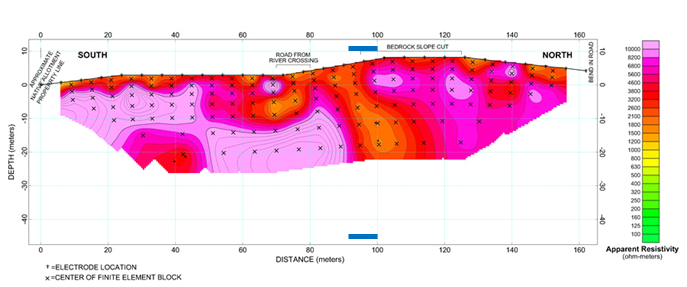
The end product from a DC resistivity survey is generally a cross section showing thicknesses and resistivities of the geoelectric layers. These sections are created through inverting the apparent resistivity data into a modeled resistivity depth section. more
Ground truth data from well logs or drill holes will constrain the model and enhance the interpretation. If borehole data or a conceptual geologic model is available, then a geologic identity can be assigned to the geoelectric units.
Plan maps, data presentations, inverse models, forward calculations of the same model or cross-section, and a narrative description of the work done are generally provided.
Electrical Resistivity Tomography (ERT)
 ERT is high-resolution DC resistivity data processed using modern tomography imaging techniques. The dense data collected provide the basis for solving sophisticated inverse computer models of the conductivity distributions of the ground. more
When both resistivity and induced polarization are measured, the resulting data set relates to the complex impedance of the earth and the term “EIT” (Electrical Impedance Tomography) is sometimes used to describe the geophysics method, particularly when the transmitters and receivers are down-hole.
ERT involves the acquisition of hundreds, even thousands, of four-electrode resistivity measurements that are possible between multiple strings of electrodes. For example, given two strings of 15 electrodes (30 electrodes total), there are 632 different dipole-dipole measurements that can be made (including all reciprocal measurements) involving transmitter and receiver dipoles with a fixed length of two electrode spacings.
To measure all of the desired transmitter-receiver electrode combinations requires a computerized acquisition system that automatically switches both transmitter and receiver electrodes and has multi-channel measurement capabilities, such as the Zonge ZETA™ instrument system.
ERT/EIT applications
ERT is often used to generate resistivity images of the plane defined by the space between two boreholes (or other electrode strings), and can be used effectively in secondary petroleum recovery.
Zonge’s ZETA™ data acquisition system has expanded the use of ERT to multiple environmental problems such as:
- Hazardous waste site characterization
- Mapping of landfill size and depth extent
- Monitoring fluid-injection processes
involved in waste-site remediation - Plume migration
- In-situ leaching
- Heap-leach monitoring
- Tank monitoring