
Induced Polarization, Time-domain IP & Complex Resistivity (IP,TDIP,CR)
Overview
Resistivity and Induced Polarization (IP) are commonly-used geophysical survey methods for measuring the electrical properties of subsurface rock.
Both measurements are made by introducing a controlled electrical current into the ground using two current electrodes, thus energizing the ground, and then measuring the induced potential-field gradient voltage at (between) two non-polarizable receiver electrodes. The distance between the pair of current electrodes and the pair of potential-field electrodes determines the depth of investigation (the measured data).
The resulting voltages as a function of time (time-domain IP/TDIP), are recorded digitally and analyzed for the “induced polarization” effect. The measured IP phase indicates the ability of rocks to briefly hold an electrical charge after the transmitted voltage is turned off.
How it works
Electrical properties of the ground can be calculated from comparing the transmitted signal to the received signal. Ground resistivity (ability to conduct an electrical current) affects the strength of the received signal. A change in induced polarization (ability of ground material to polarize at interfaces) affects the shape or timing of the received waveform.
When plotted, these properties reveal valuable information about faults, fractures, geologic structures, mineralization, and groundwater porosity for subsurface modeling.
Applications
Resistivity and IP surveys are used extensively in minerals, geothermal, and groundwater exploration, in many environmental investigations, and for several applications in hydrocarbon exploration and secondary recovery. Resistivity surveys are also an underused but valuable tool for many geotechnical applications.
The polarization data from an IP survey adds insight for interpreting results of other common exploration survey methods. IP surveys may be done as follow-up to a CSEM or CSAMT survey (in which an induced, controlled source of electric energy is also used, but in this case, to measure the magnetotelluric fields).
CSEM / CSAMT provides better resolution and deeper information than IP. Thus CSEM / CSAMT is often used for reconnaissance of larger geographical areas to locate faults and resistive anomalies, followed by selective IP investigation to prioritize drill targets.
Complex Resistivity
![]() Complex resistivity (CR), also known as Spectral IP, is a multi-frequency IP method developed by Kenneth Zonge in the early 1970s as a means of differentiating between anomalous survey responses coming from geologic alterations, from sulfides, or from electromagnetic coupling — an unwanted artifact of the IP measurement process itself. more
Complex resistivity (CR), also known as Spectral IP, is a multi-frequency IP method developed by Kenneth Zonge in the early 1970s as a means of differentiating between anomalous survey responses coming from geologic alterations, from sulfides, or from electromagnetic coupling — an unwanted artifact of the IP measurement process itself. more
Measurements are made over two or three decades of frequencies to better determine the source of the IP response. This method has proven extremely valuable for mineral reconnaissance surveys. The early model Zonge GDP released in 1976 was the first commercially available, digitally-controlled, IP/CR receiver.
Geology
The geologic model is of disseminated mineralization in which the conductive sulphides are not connected but occur in an insulative matrix. Clay minerals also show a moderate IP effect. Variations in subsurface moisture content, porosity, permeability, and soil or rock type all affect resistivity measurements. Changes in imaged resistivities are used to infer changes in geology. more
Relatively few conditions create an IP response. Metallic mineralization — particularly disseminated sulphides — cause increased IP values. Certain dissolved solids in groundwater increase IP response, and clay can increase IP response if the abundance of it is within specific ranges (dependent on clay type).
In structural features, such as faults, contacts generally appear as conductive plates or sheet-like features unless they have been well cemented with little porosity. For example, quartz or calcite-filled veins could be expected to have high resistivity values. In contrast, porous shear zones could be expected to have low resistivity values (relatively conductive). Likewise, alteration products can be extremely conductive (clay-based alteration) or extremely resistive (silicification zones).
Principles
Induced polarization (IP) is a measure of a delayed, voltage response in earth materials. The IP effect is caused by a current-induced, electron-transfer reaction between electrolyte ions and metallic-luster minerals, a measurement of the capacity of the earth to store electrical energy. more
The IP effect can be determined by passing an induced current into the ground and measuring the change in voltage with respect to time (time-domain IP/TDIP), or by measuring changes in phase at a given frequency with respect to a reference phase (frequency-domain IP/FDIP).
To produce an IP effect, fluid-filled pores must be present, since the rock is basically an insulator. The IP effect becomes evident when these pore spaces are in contact with metallic-luster minerals, graphite, clays or other alteration products. IP effects make the apparent resistivity of the host rock change with frequency. Generally, the rock resistivity decreases as the measurement frequency increases.
Field Logistics
Specialized transmitters and voltage recorders are used to measure IP effect. Zonge geophysical equipment used for Resistivity-IP surveys acquires both data sets simultaneously. Electrodes for the current are dug into the ground and separate, non-polarizing electrodes are used to sense the impressed voltages. A motor-generator is required for deep investigations. more
Zonge crew size is typically three to five people with a single pickup truck. No mechanized equipment is used. No earth moving or trenching is needed. Wires, electrode stakes, and survey flagging are removed and the electrode positions are raked when the survey is completed, leaving little or no evidence that the survey occurred.
The transmitter dipole consists of thin, 14-gauge insulated wire laid on the ground. At each end, the wire is connected to the ground with metal stakes, each about ½ inch in diameter, pounded into the ground one to two feet. These stakes are doused with saltwater to provide good electrical contact. The group of stakes pounded into the ground at each end of the wire is called an “electrode.”
Numerous electrodes are set up in a line and connected by wires to the transmitter at a central location. The wire is laid out by walking. Vehicle access along the length of the wire is not necessary. Transmitter equipment is typically kept in a truck with a generator mounted in the back or on a small trailer behind it.
Measurements are made with a man-portable receiver by connecting to different dipoles. The receiver dipoles are also wires laid on the ground, but in this case, they are grounded using small, ceramic “pots” about six inches tall and two inches in diameter, embedded slightly into the soil. The receiver equipment is carried along the survey line by the operator while making measurements at different locations.
The geometry between the transmitter and receiver electrodes varies with different types of electrode arrays. A frequently-used configuration is the dipole-dipole array in which current is introduced into the ground at two adjacent (current) electrodes and the resulting electric field is measured at two adjacent (potential) electrodes. The distance between the current electrodes is generally the same as the distance between the potential electrodes.
As the spacing between the two sets of electrodes is increased, the relative contribution of responses from rocks at depth is increased, providing information on the variation of resistivity and IP effects with depth. The depth of investigation for a given array configuration is a function of the relative resistivity contrasts and the electrode spacing.
Modeling and Deliverables
Computer programs are used to convert and model the measured data as images of the electrical structure of the subsurface. These images include profiles of resistivity and IP versus depth. Models with interpretation relative to your target or objectives, along with the measurement-station locations indicated and relevant acquisition parameters, should be included in the deliverables. more
Results can be presented in several forms:
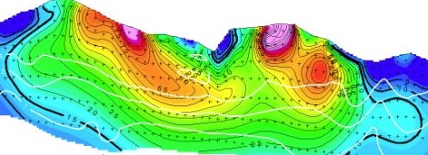
- Modeled cross-sections (profiles) of contoured resistivity in ohm-meters and IP data in milliseconds, for each line of data collected
- Plan views at a constant elevation or depth, which aid to reveal trends between data collection lines
- Diagrams showing 2D cross-sections in a three-dimensional context
Resistivity and IP surveys measure “apparent resistivity” and “apparent polarization.” These are a function of the variation in intrinsic resistivity and polarization within a volume of earth, not the actual values at specific plot points. The distribution of intrinsic values for resistivity and IP effect is then interpreted from the measurements using theoretical curves and computer modeling.
Smooth-model inversion is the modern method for converting resistivity and IP measurements to smoothly-varying, model cross-sections. Inversion mathematically “back-calculates” (inverts) from the measured data a likely location, size and depth of the sources of IP and resistivity changes. Resistivity and IP values are iteratively modified until the calculated values match the observed data as closely as possible, subject to certain constraints.
Considerations
Non-economic minerals dominate geology. Iron sulphides (pyrite) live up to their reputation as fool’s gold. Both resistivity and IP data can also be influenced by cultural features (man-made objects such as fences, power lines, pipelines, etc.). Knowledgeable survey design can minimize these effects, but experienced interpretation is necessary to obtain the most useful information.